Every piece of equipment was chosen for its technical performance, reinforcing the quality of our maintenance work.
 Lathe · in process
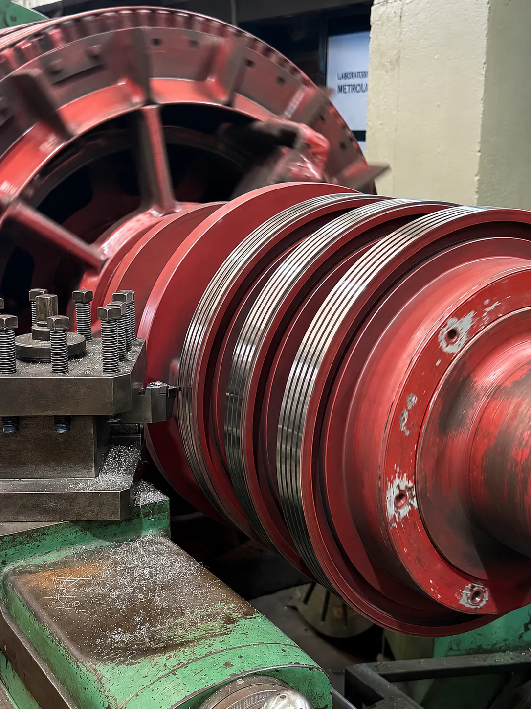
 Our precision lathe restores the original geometry of shafts and housings with tolerances of 0.01 mm and diameters up to 800 mm, ensuring the dimensional fit every motor requires.
Measurement of the component to determine wear, eccentricity and deviations from the original design.
Selection of tooling and cutting parameters adapted to the material and the required profile.
Execution with real-time tolerance control, ensuring Ra and fit dimensions.
Final dimensional check: calibrated micrometer, dial indicator and roughness gauge.
 IRD
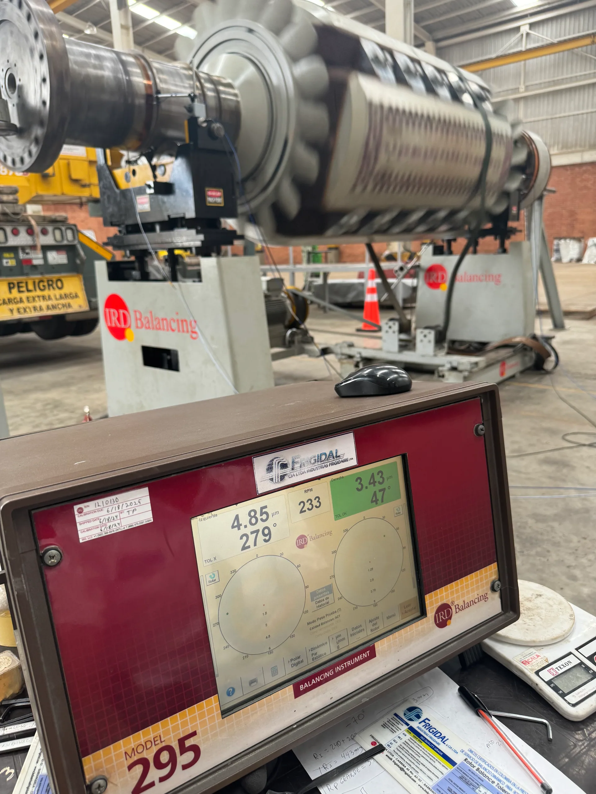
IRD The IRD bench eliminates imbalance in rotors, preventing vibrations that shorten the life of bearings, seals and structures.
The rotor is installed on calibrated supports to ensure coaxiality and measurement reproducibility.
The IRD system measures imbalance mass and angular position in the two correction planes.
Mass is added or removed in the defined planes until reaching grade G1.0 or better.
Report of residual levels and ISO 1940 certificate of conformity included with delivery.
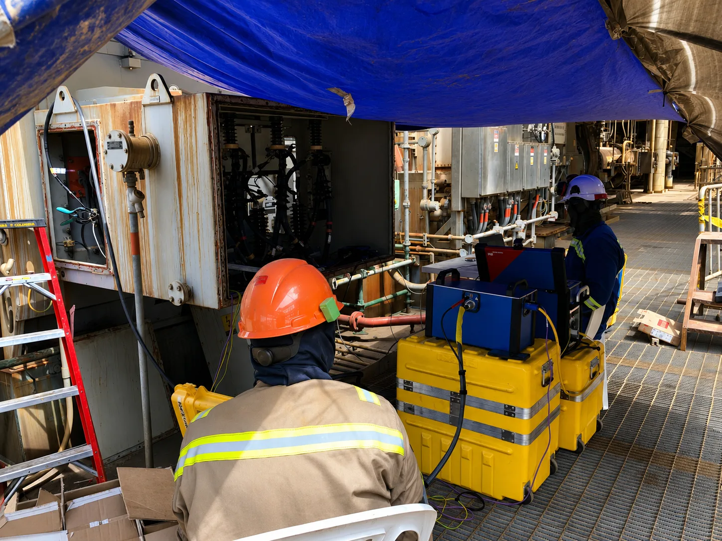
 SKF Microlog · in the field
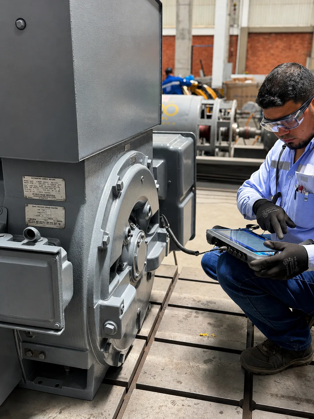
 The SKF Microlog analyzer captures vibration signals with high-density FFT resolution, detecting bearing and winding defects before they cause unplanned downtime.
Mounting sensors at strategic points: DE, NDE, free shaft and housing, per ISO 10816.
High-resolution FFT processing to identify the characteristic frequencies of each rotating component.
Correlation with defect frequencies: BPFO, BPFI, BSF, GMF and running harmonics.
Report with severity by band, historical trend and priority intervention recommendation.
 FLIR · in the field
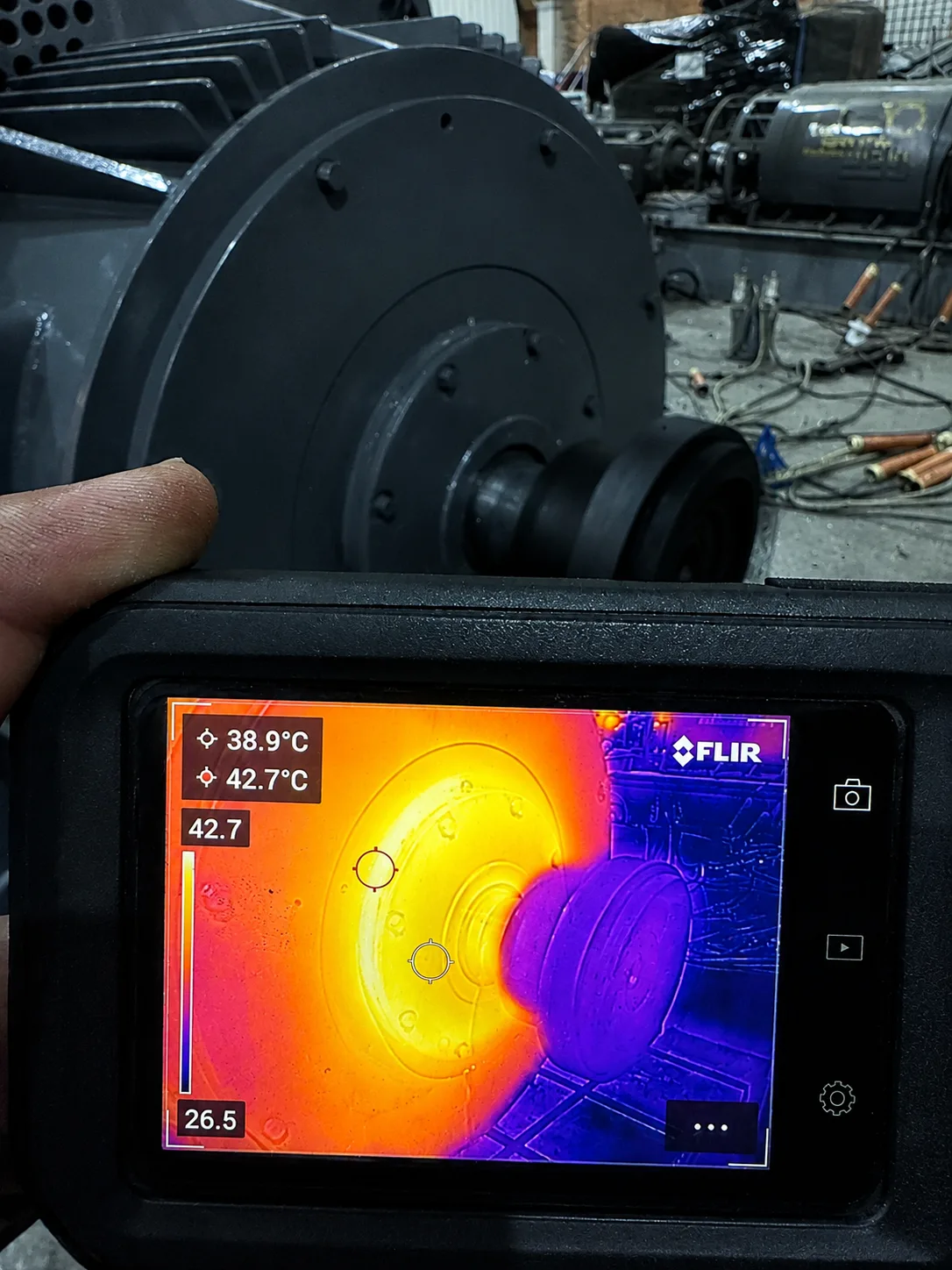
 The FLIR thermal camera detects temperature gradients with accuracy, identifying hot spots in connections, windings and bearings invisible to the human eye.
Capture with the equipment at nominal load and stabilized temperature to obtain representative data.
Correlation of the thermal map with the electrical and mechanical condition to determine the source of the heating.
Thermograms, severity classification and corrective-action recommendation.
The silent enemy of a winding is the microscopic air voids between turns: that’s where thermal failure begins. The VPI process eliminates them completely and seals the winding into a single solid mass.
Inside the tank, the air and moisture trapped in the winding are extracted until it reaches absolute vacuum.
The winding is submerged in class H impregnation resin.
Pressure is injected to force the resin into the coil, where air no longer exists.
The assembly is baked until it solidifies: the insulation becomes monolithic, with no bubbles or weak points.
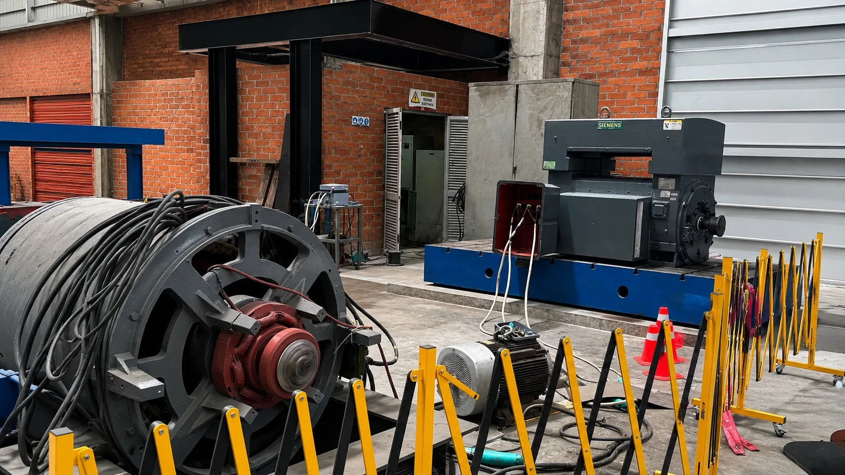 Bench · 7,000 V
 On our no-load bench up to 7,000 V we verify current and voltage under no-load conditions, certifying electromagnetic performance at nominal voltage and speed before delivery.
Coupling of the motor to the bench with verification of supply parameters and insulation before startup.
Progressive startup sequence recording inrush current and no-load acceleration time.
No-load operation with continuous monitoring of current, temperature and vibration in bearings and housing.
Automated recording of no-load characteristic curves: current, PF and heating. Technical report included.
 Diligens · on the bench
 Diligens combines exclusive Omicron technology and an extensive international database to diagnose the dielectric condition of any machine — before and after each intervention.
DC resistance measurement of windings and dielectric evaluation via polarization index to establish the baseline condition of the insulation.
Analysis of polarization and depolarization current, dielectric discharge and progressive voltage ramp to characterize the insulation system in depth.
Exclusive Omicron technology with PRPD analysis — detects, quantifies and locates partial discharges and their byproducts; identifies dielectric defects before they cause failure.
Dissipation factor, capacitance, surge (turn-to-turn impulse) test and visual endoscopic diagnosis.
Final analysis based on a database and certified equipment from international cooperation.